


A long time ago, in a galaxy called Manhattan, Vern Gillman devised an ingenious way to run his scratch built, O scale, subway and elevated cars using an outside 3rd rail for power pickup, similar to the real ones. After all, the O scale trolley modelers ran their cars using the overhead trolley wire for pickup, so why shouldn't the rapid transit cars get their power in a realistic manner as well! Here we attempt to show the basic process of the 3rd rail shoes are made and the options available to provide a working 3rd rail setup.
Our 3rd rail was made to be used on a portable, modular layout. It may seem crude by some standards, however it holds up pretty well and can be adjusted as needed. We established our own standard for the placement of the 3rd rail to suit our needs and still look like rapid transit type 3rd rail. We do not use NMRA standards for this.
When making the shoes, a little trial and error may be necessary at each step, but with practice you will end up with a set of working 3rd rail shoes. Study the pictures, enlarge them by clicking on them.
Measurements mentioned above can be off by about 1/32" in either direction. It will never be 100%, but always try to be as close as possible.

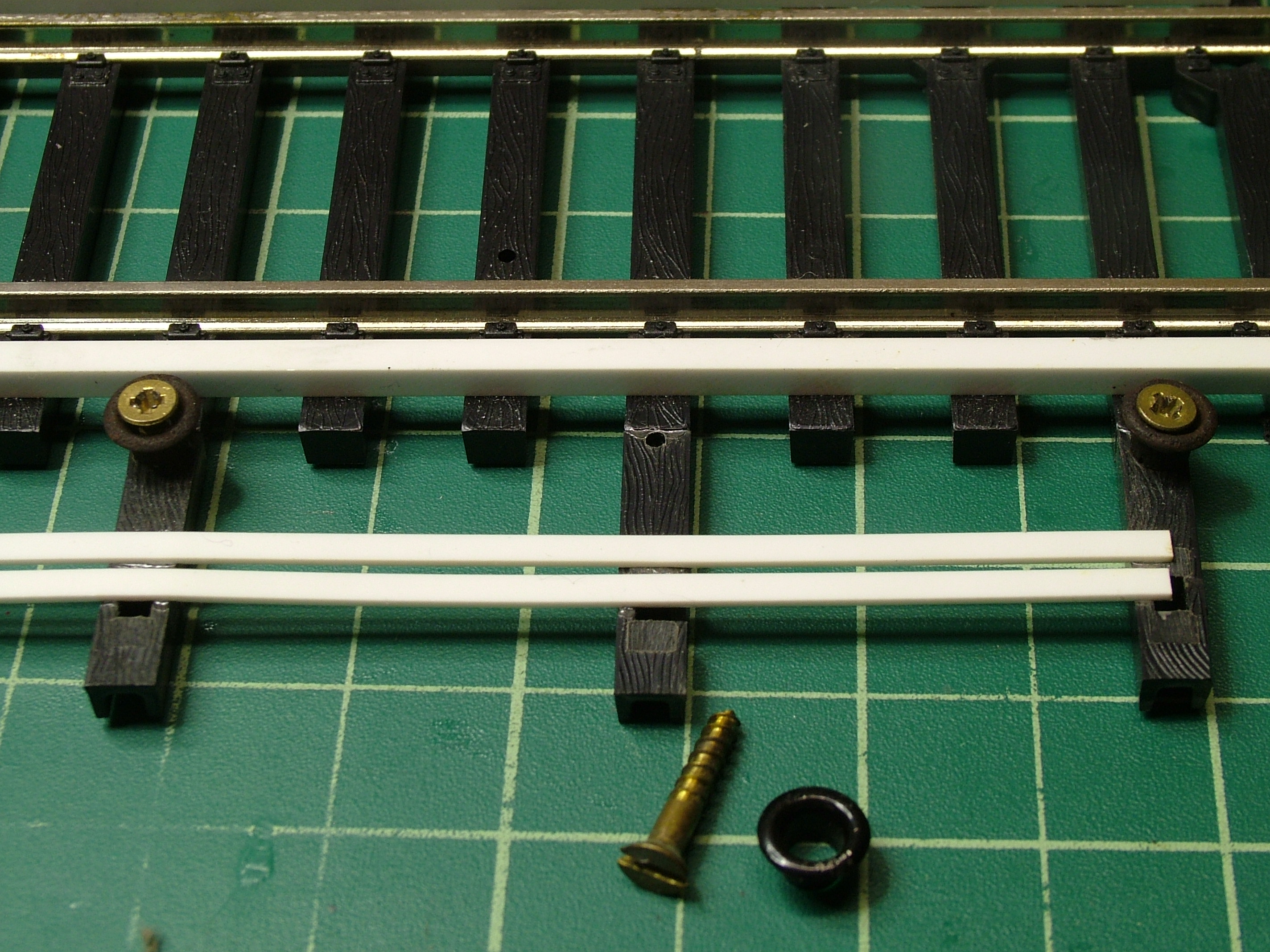
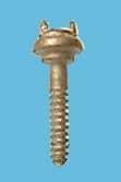
The photos above show our "home-made" 3rd rail chairs. They are made using #000 (5/32") eyelets with a #2 1/2" brass wood screw. The code 125 rail is soldered to the top of the screw. Adjustments are made to each chair before soldering, to insure the correct height. The 3rd rail ties are 3/4" long pieces cut from O scale wood ties. Please note the photo on the right above shows an elevated track section using this method as a trial. It won't work because the soldering process will melt the plasitc ties. The photos below show a better way to install the 3rd rail in plastic ties, using Q-Car Co. cast 3rd rail chairs (CS-002).

While planning a track layout, think about the placement of the 3rd rail. For example around curves it's best to place the 3rd rail on the outside of the curve. At stations the 3rd rail is usually opposite the platform. Interlockings present the biggest challenge. The 3rd rail will be broken up wherever the track diverges. The 3rd rail shoes on the cars will need clearance, as the car comes across from one track to another. Also, small ramps can be made from sheet tin and soldered to the 3rd rail where the shoes need to be guided onto the rail, in places the 3rd rail can't be broken. The photos below show examples of this.


The process shown here is for installation on Q-Car Co. General Steel Industires "SMEE" (R-10 to R-62) trucks. This can be adapted for most any truck you may want to use.
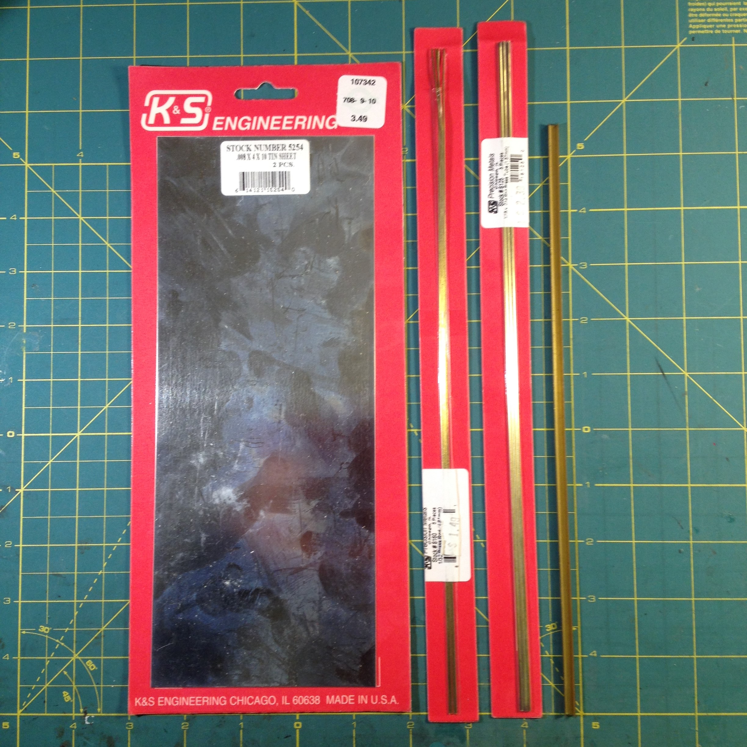
Starting with the tin sheet, cut out a strip that is 5/32" wide, using sheet metal shears. Cut pieces (4 per car) from the strip about 5/8" long. At one end of each strip, make a slot for the spring, leaving about a 1/16" on either side of the slot.
Prepare the 1/16" brass tubing by "tinning" the surface with solder. Then slice off approximately 1/16" pieces - 2 per shoe. Next, bend and apply solder to the 2 tabs created on the ends of the shoe cut from the 5/8" long strips of sheet tin. The bend is made to accept the 1/16" tubing pieces.
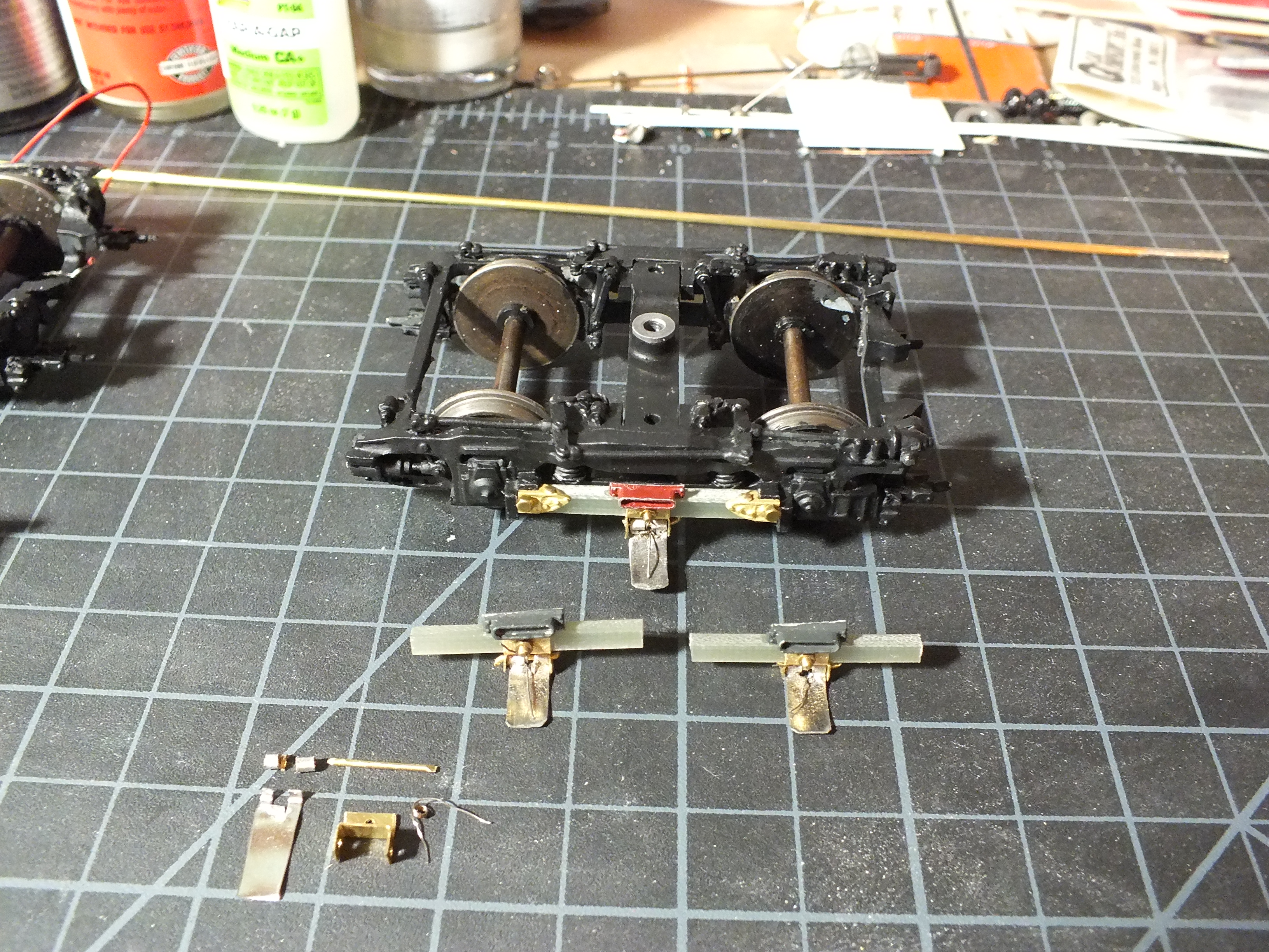

Using the 3/16" square channel (or use .015 thick sheet brass) fabricate the shoe hanger. The hole drilled on the top is to be large enough for a 00-90 screw to pass through freely. The side holes drilled for the 1/32" brass rod to pass through.
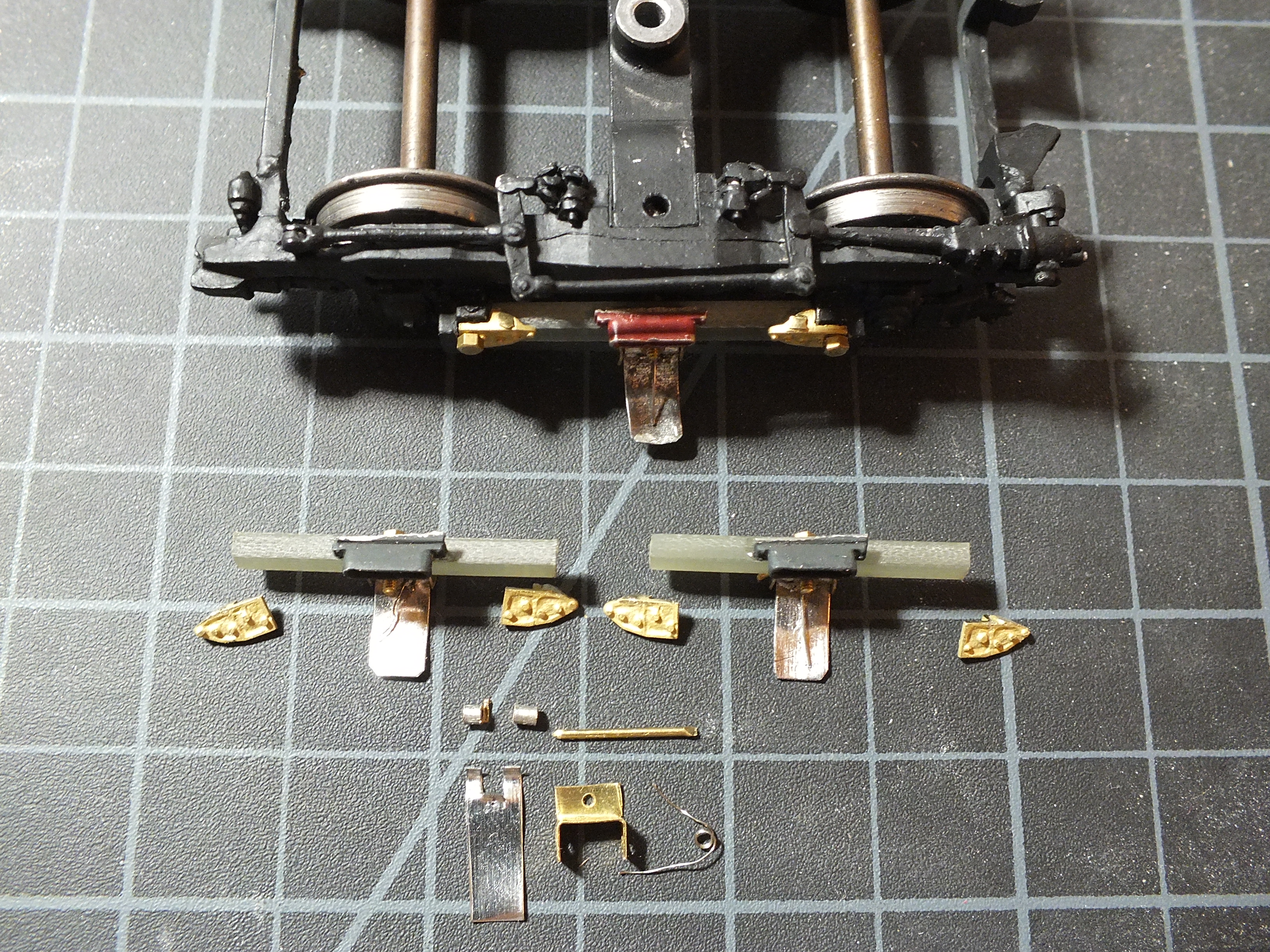
Place the tinned 1/16" tubing pieces on the bent tabs on the end of the shoe and solder in place. The ends of the tabs holding the tubing should pass or stick out slightly past the tubing to act as a stop for the shoe, so it won't hang down too far past the 3rd rail and get snagged on the running rail.
Cut a length of the 1/32" brass rod long enough to pass through the entire hanger with enough on each end to crimp, after assembly.
Make a spring from the Q-Car pole spring by unravelling a bit then leave two or three loops intact, then unravel a bit more on the other end of the loops. If you like, you can make a spring from scratch using .010 music wire.
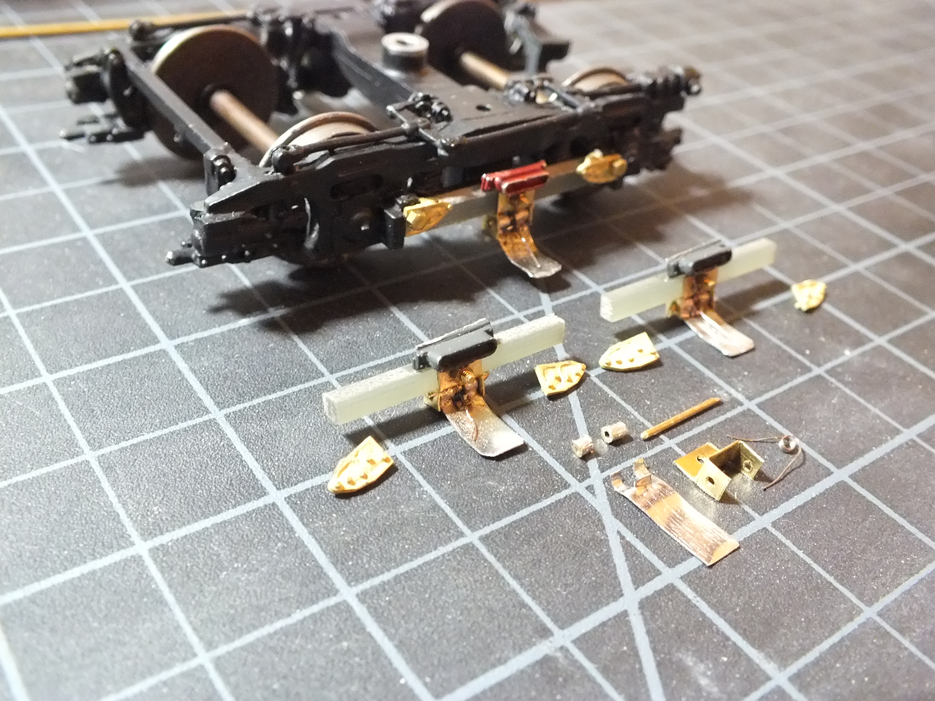
Place the spring in the notch between the 2 tubes on the end of the shoe while inserting the shoe assembly into the hanger, lining up the holes in the hanger with the tubing and the spring. Then pass the brass rod through the hanger, tubing, and spring! Making a point on one end of the brass rod will help pass it through. I know it's very difficult to hold all the pieces in place while trying to insert the brass rod through. It may take several attempts and you may lose the spring in the process, so be prepared! It's frustrating, but it can be done!
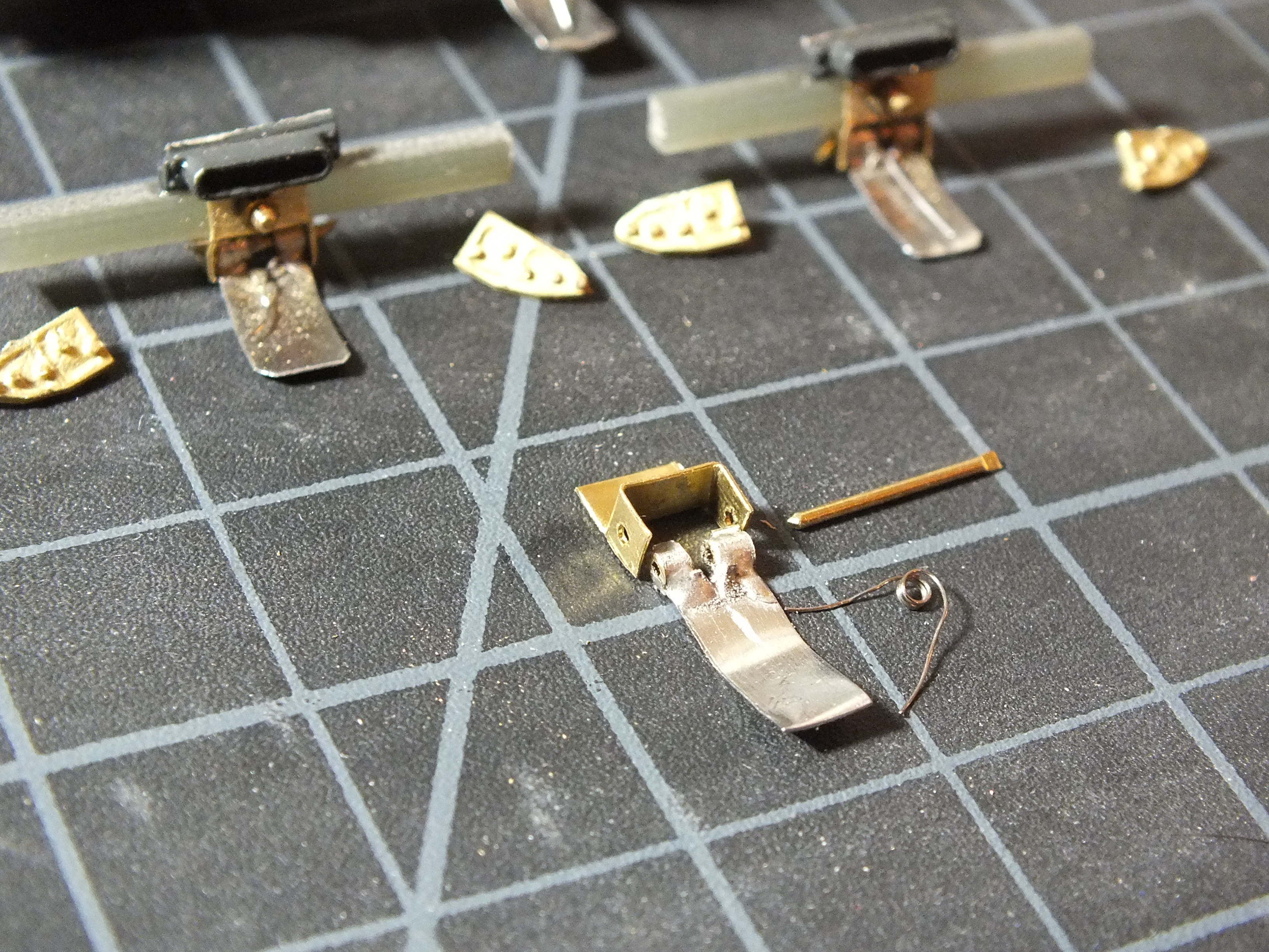
Once the rod is successfully inserted, crimp each end of it to keep it there. If this was all done correctly, the shoe should move up and down freely and the back of the shoe should hit the top of the hanger and stop it from hanging too far down. Adjustments will have to be made to make sure it contacts the third rail correctly. Bending the shoe so it has the right contour for proper contact will need to done, once installed on the truck.
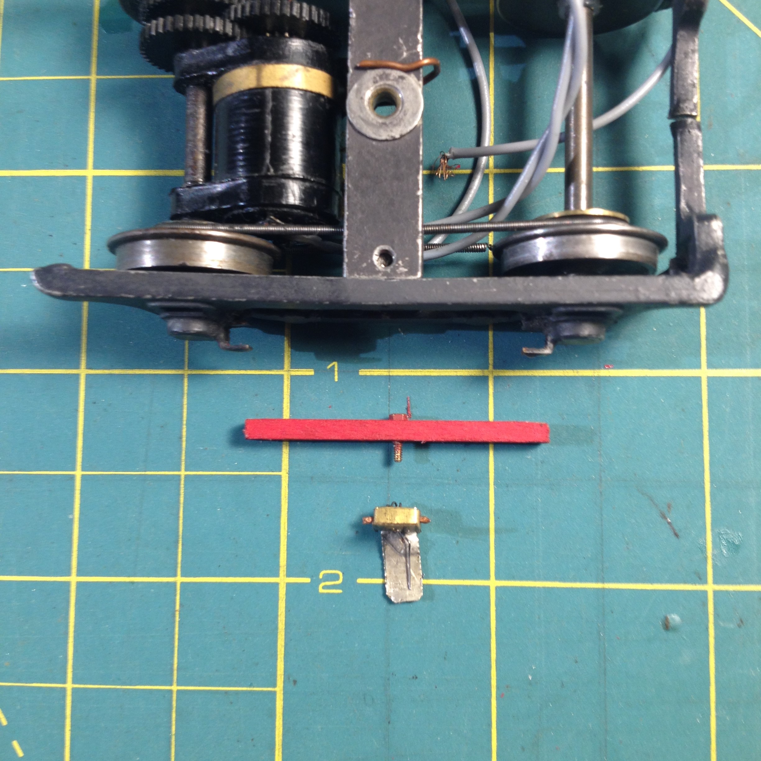
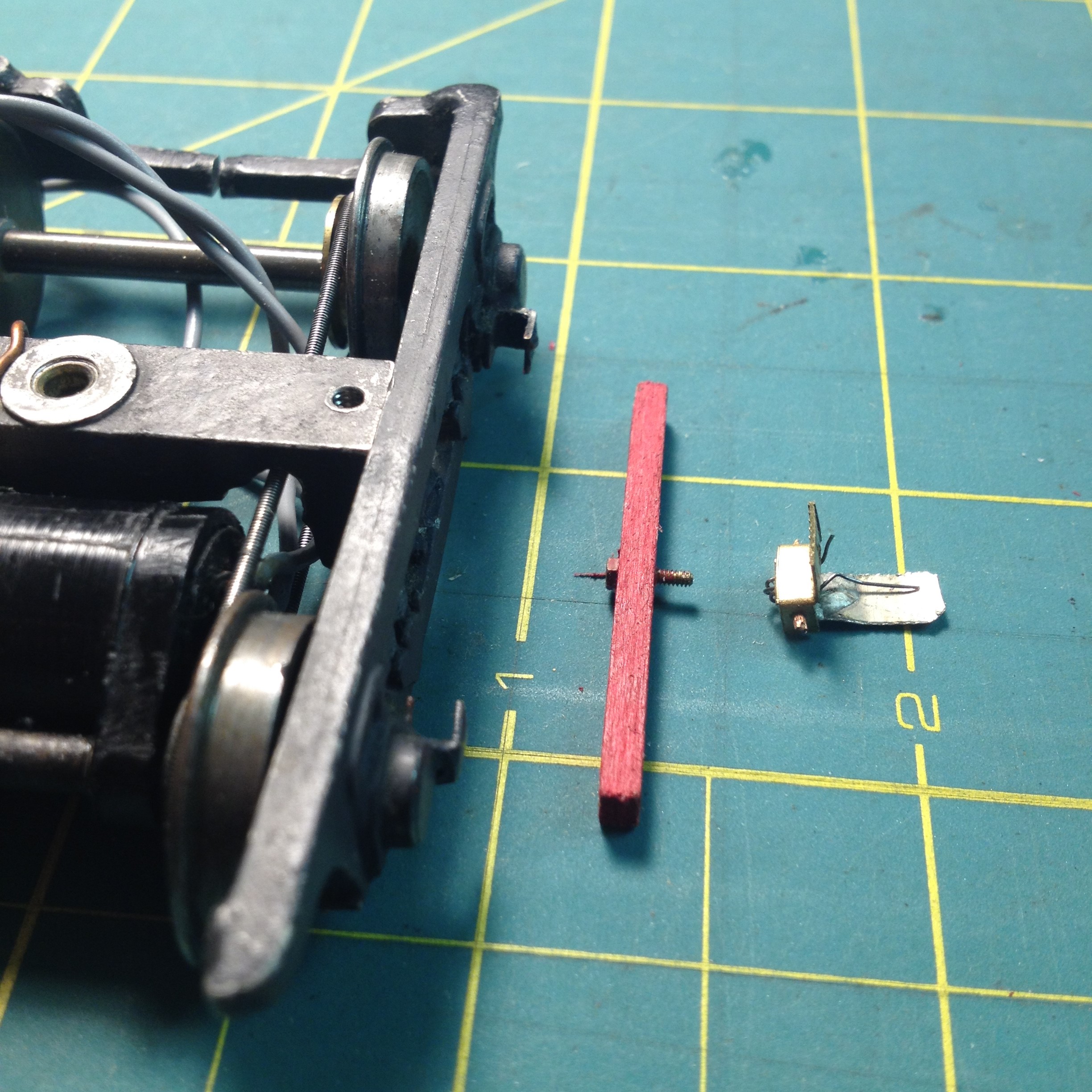
Make shoe beams from the material of your choice. Most of the beams on our cars are made from bass wood. Pictured above is some type of fiber board cut into strips. Cut the beams to the length between the brackets that hold the beam in place on the truck. The beam should fit snug between the brackets.
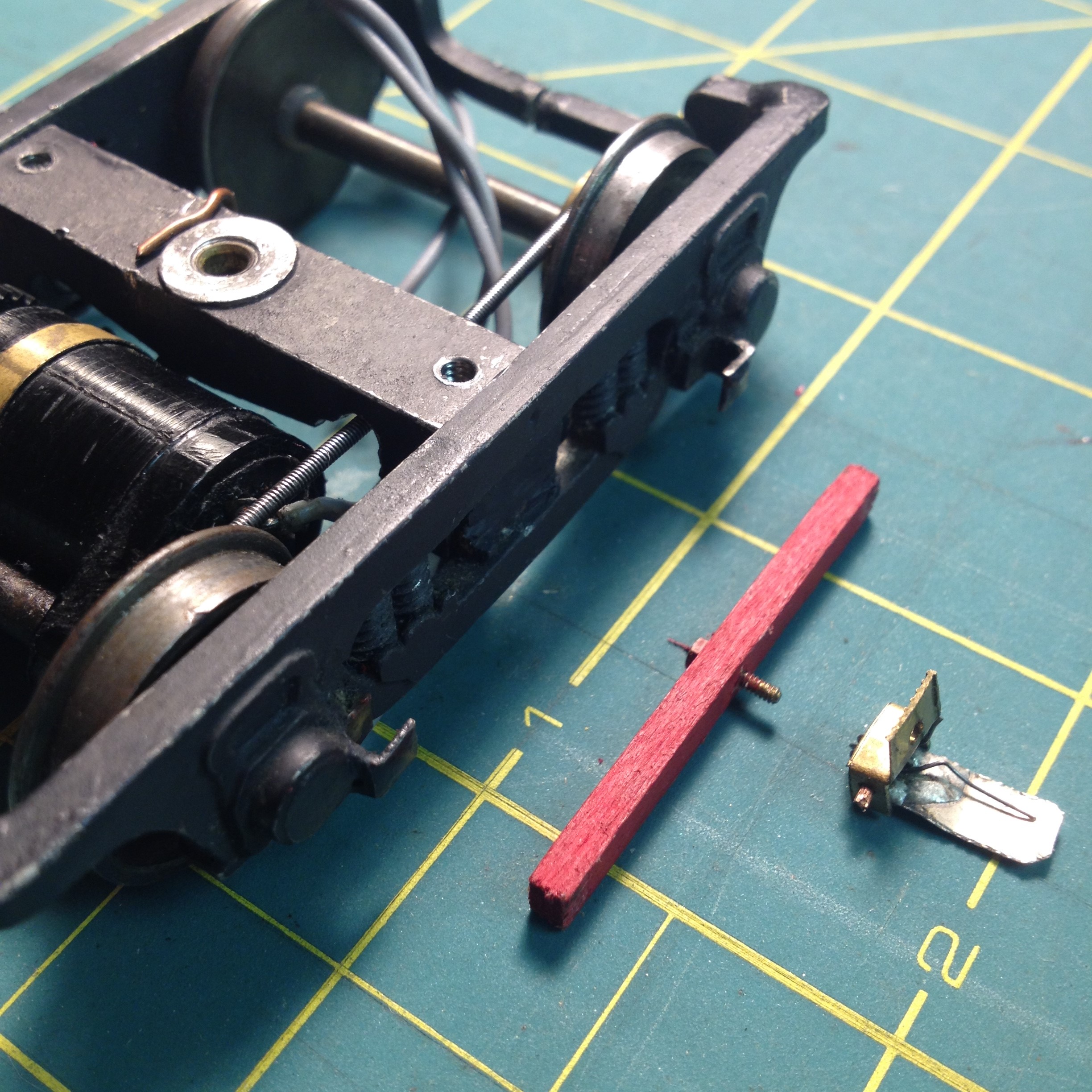
In the center of the beam, using a .035 bit, drill a hole for the shoe hanger. Tap the hole with a 65 tap for a 1/4" 00-90 hex head screw. The screw is inserted from the back of the beam. Counter sink the hole, so the hex head can be slightly embedded into the beam and will fit tightly. Now you can hang the shoe assembly from the exposed screw. Secure with a 00-90 washer and nut.
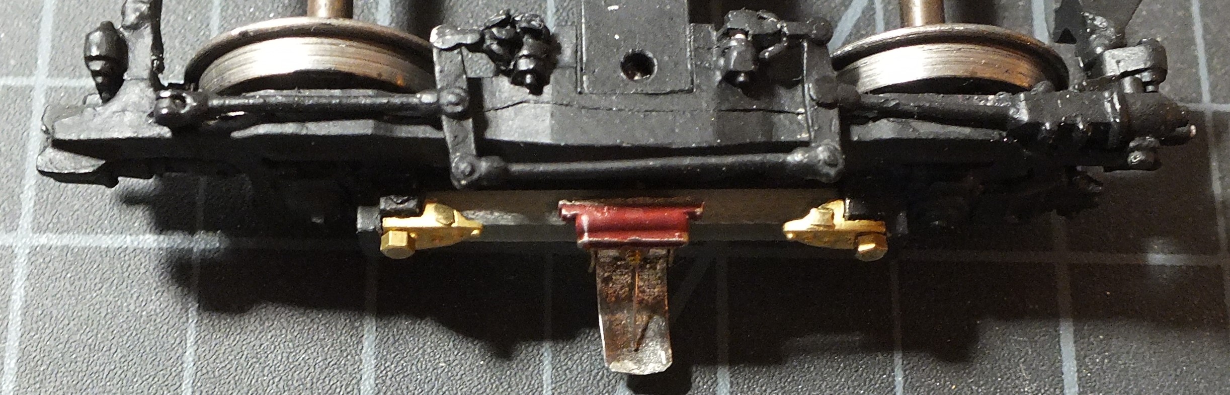
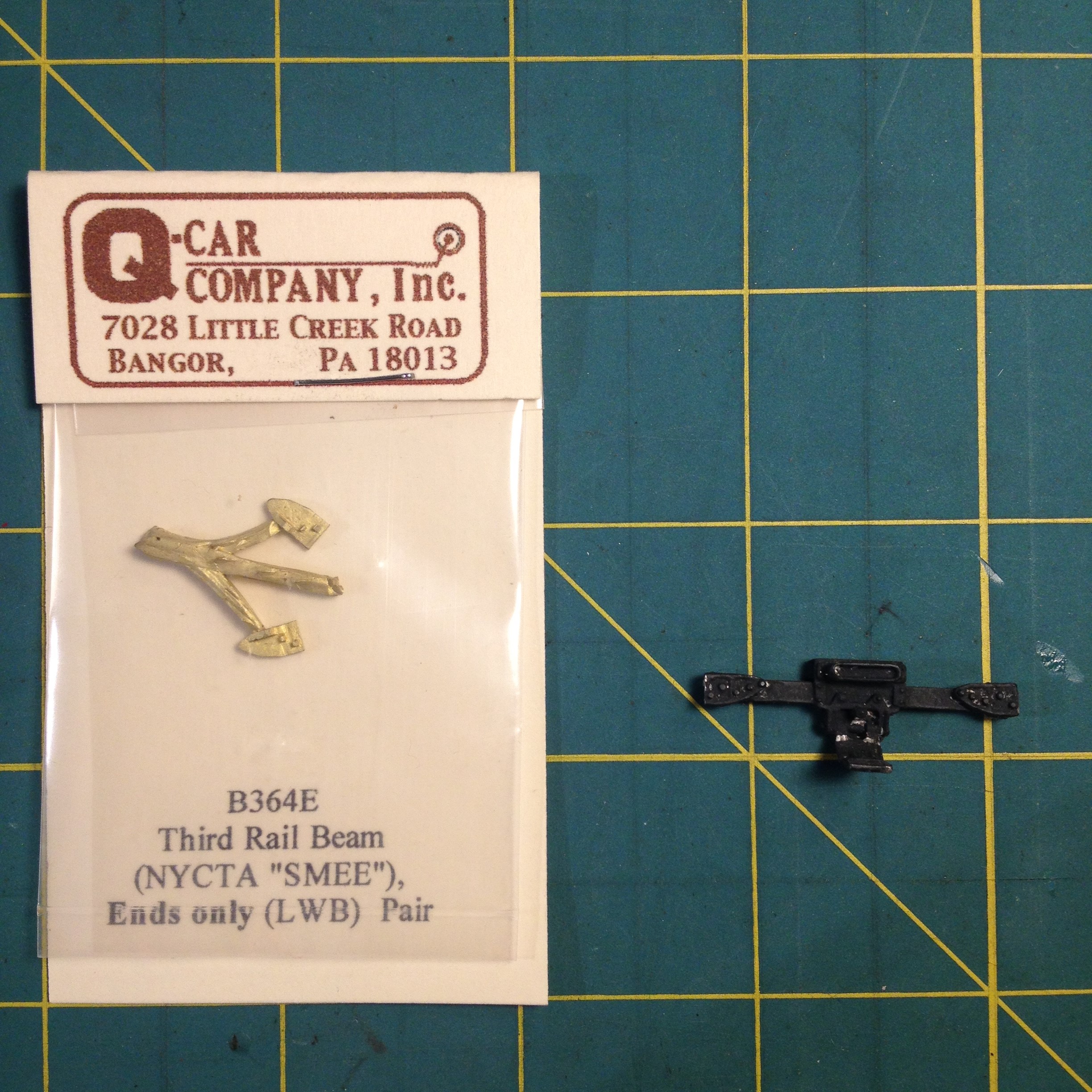
The Q-Car Co. beam end castings (B-364E) can be used to secure the beam to the truck. Test fit each beam end casting on the truck bracket and see where it makes solid contact with the bracket. You will be drilling a hole in the casting for a 00-90 hex-head screw to pass through freely - and a hole in the truck shoe bracket to be tapped for the screw. Make sure the hole in the end casting lines up with the hole in the truck shoe bracket. Secure the end castings to the truck with the 00-90 hex-head screws. The beams can be glued onto the truck with super glue by pushing the beam up into place between the brackets.
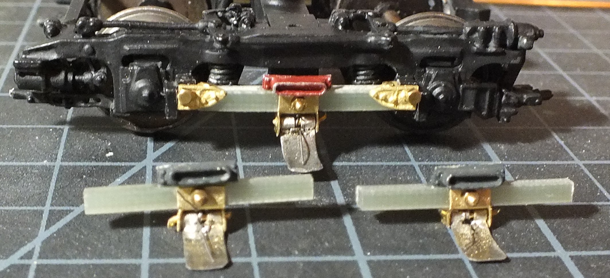
The fuse above the shoe is made by cutting one off of the Q-Car dummy 3rd rail beam white metal casting (CS-364).
Third Rail Shoes installed on a different type of truck
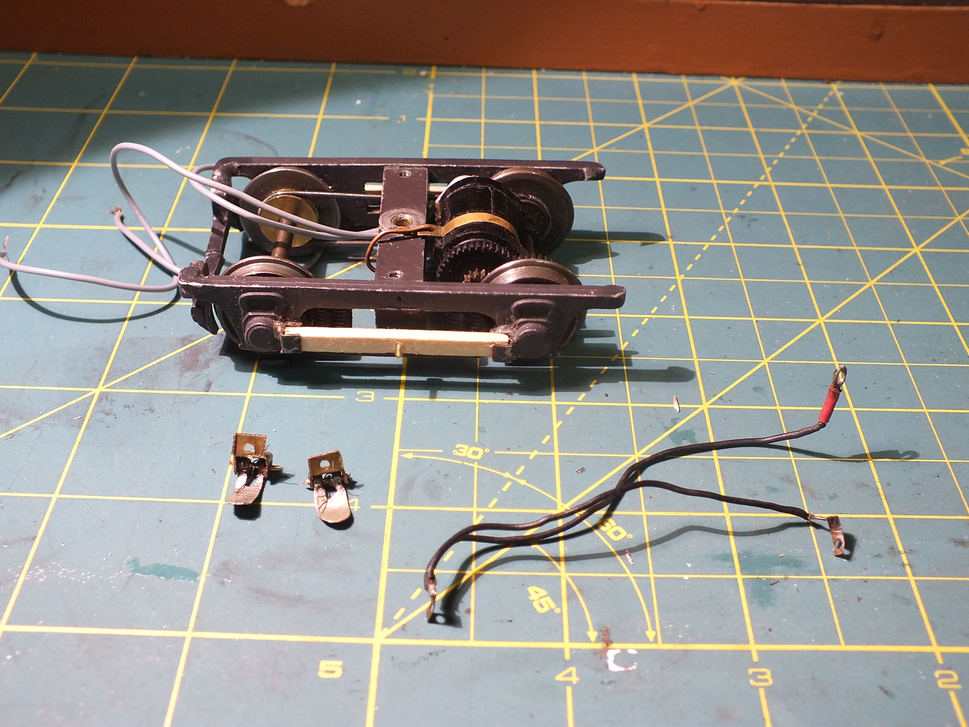
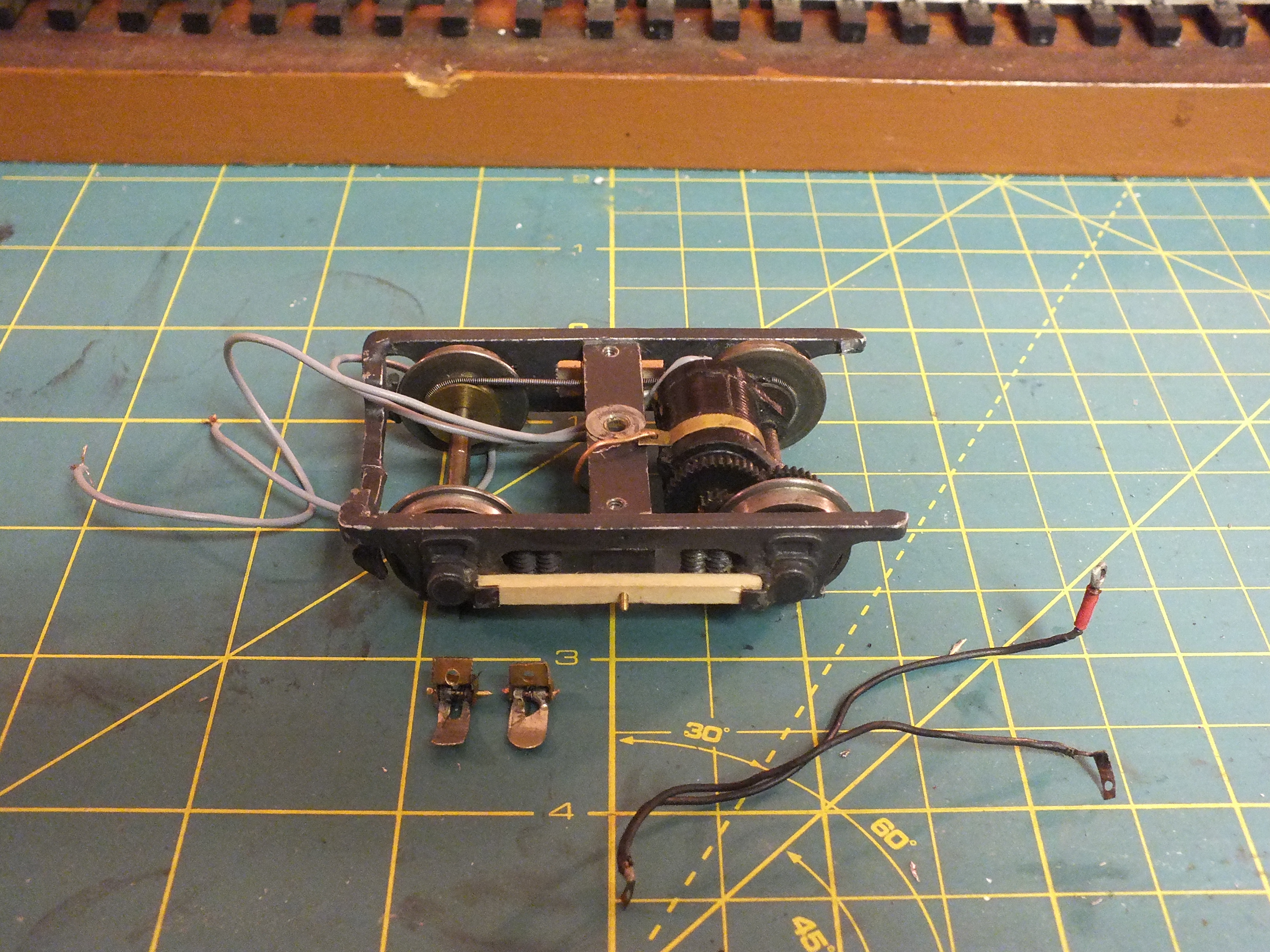
In the time before Q-Car made the GSI NYCTA Subway truck, we used Wagner IT-300 Streamliner trucks. While not correct, the truck did have a nice low profile and with a little modification, looked nice under the subway cars we were making. In order to install the 3rd rail shoe beams, we cut 1/8" square brass channel into 1/8" pieces and soldered them to the side frames just inside of each journal, making brackets. Then the basswood beam could be slid into place between the brackets.
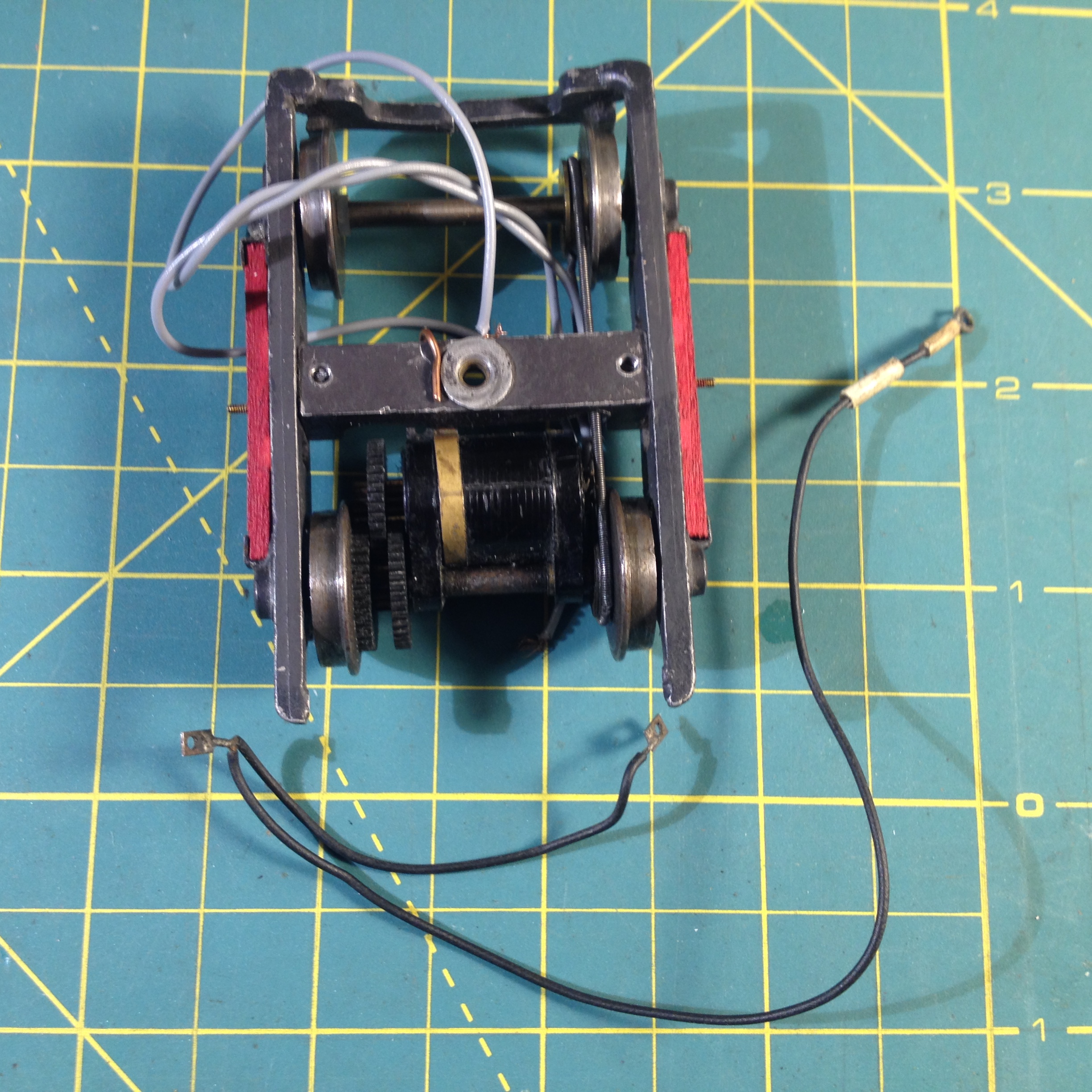
The photo on the right (above) shows the wire harness for the 3rd rail shoes. A length of wire with brass tabs soldered to each end - with holes drilled for 00-90 screw to pass through - runs from one shoe to the other. One tab has an additional wire soldered to run to the (+) motor lead.
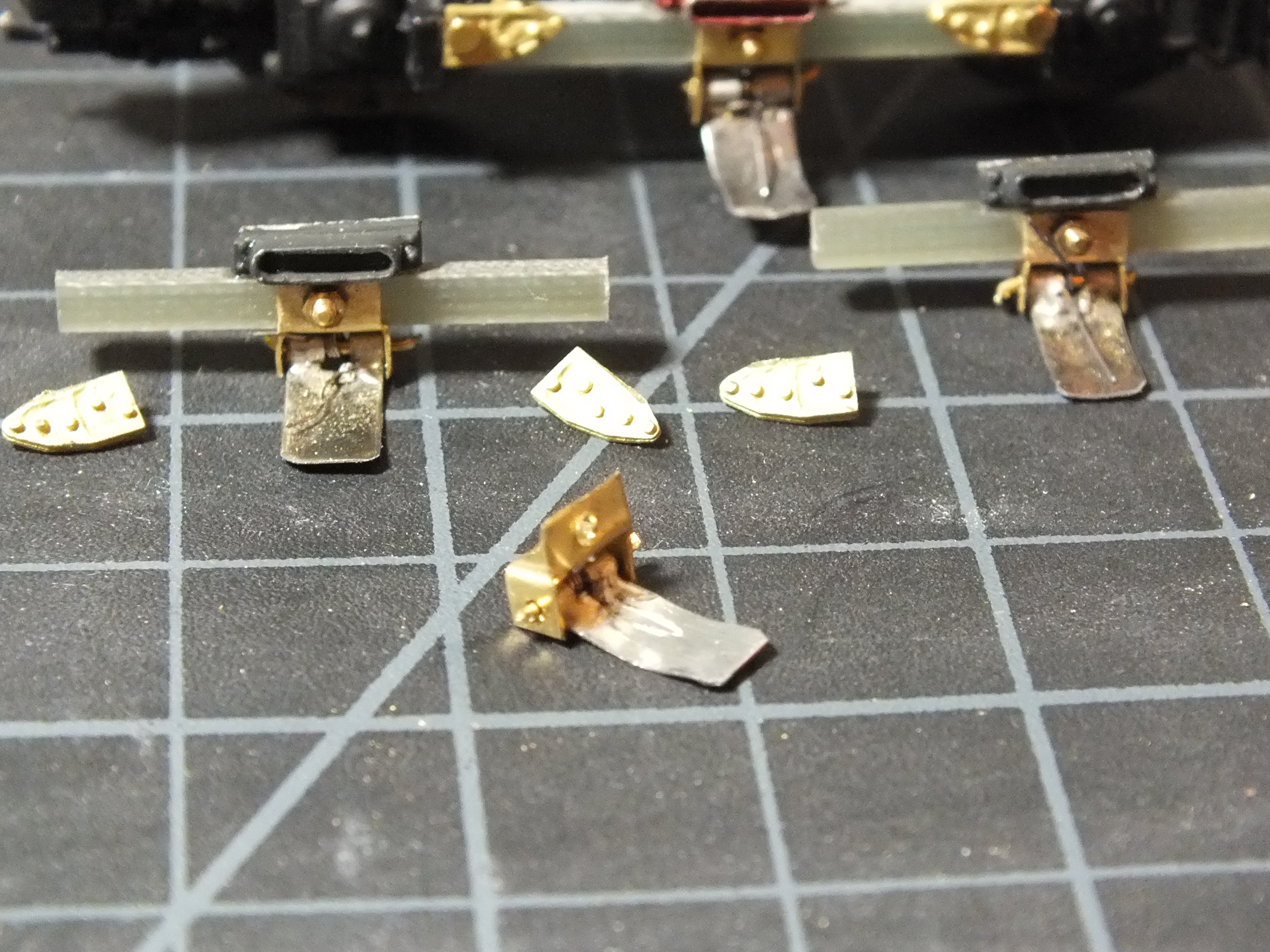
Q-Car Company Cast Brass Operating 3rd Rail Shoes
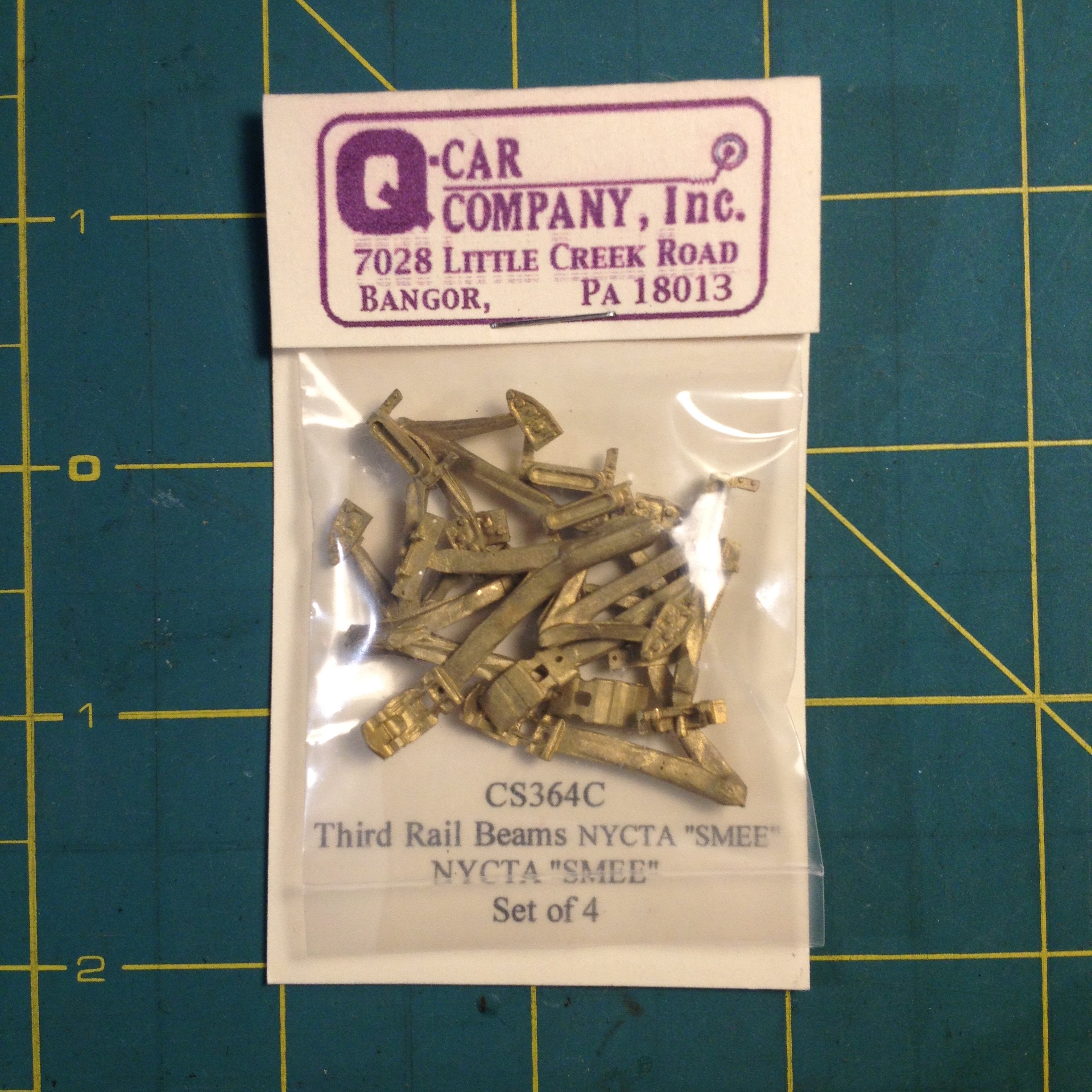
Q-Car Company makes an excellent set of 3rd rail shoe castings (CS-364-C) meant to be used with their GSI NYC Subway "SMEE" trucks. They can also be adapted for use on other trucks as well. The kit includes enough pieces to make 4 operating shoes. There is no spring included, however. A spring will need to be frabricated for each shoe, as discussed above. Once assembled and installed, the shoes work very well and look fantastic!
In order to complete the assembly of these shoes, you will also need 1/32" brass rod cut to length to use as a hinge pin. Drill out the holes in the shoe hanger and shoe itself to allow the brass rod to pass through.
Place the spring in the notch between the 2 holes on the end of the shoe while inserting the shoe into the hanger, lining up the holes in the hanger with the holes in the shoe and the spring. Then pass the brass rod through the hanger, shoe, and spring! Making a point on one end of the brass rod will help pass it through. I know it's very difficult to hold all the pieces in place while trying to insert the brass rod through. It may take several attempts and you may lose the spring in the process, so be prepared!
Once the rod is successfully inserted, crimp each end of it to keep it there. If this was all done correctly, the shoe should move up and down freely and the back of the shoe should hit the top of the hanger and stop it from hanging too far down.

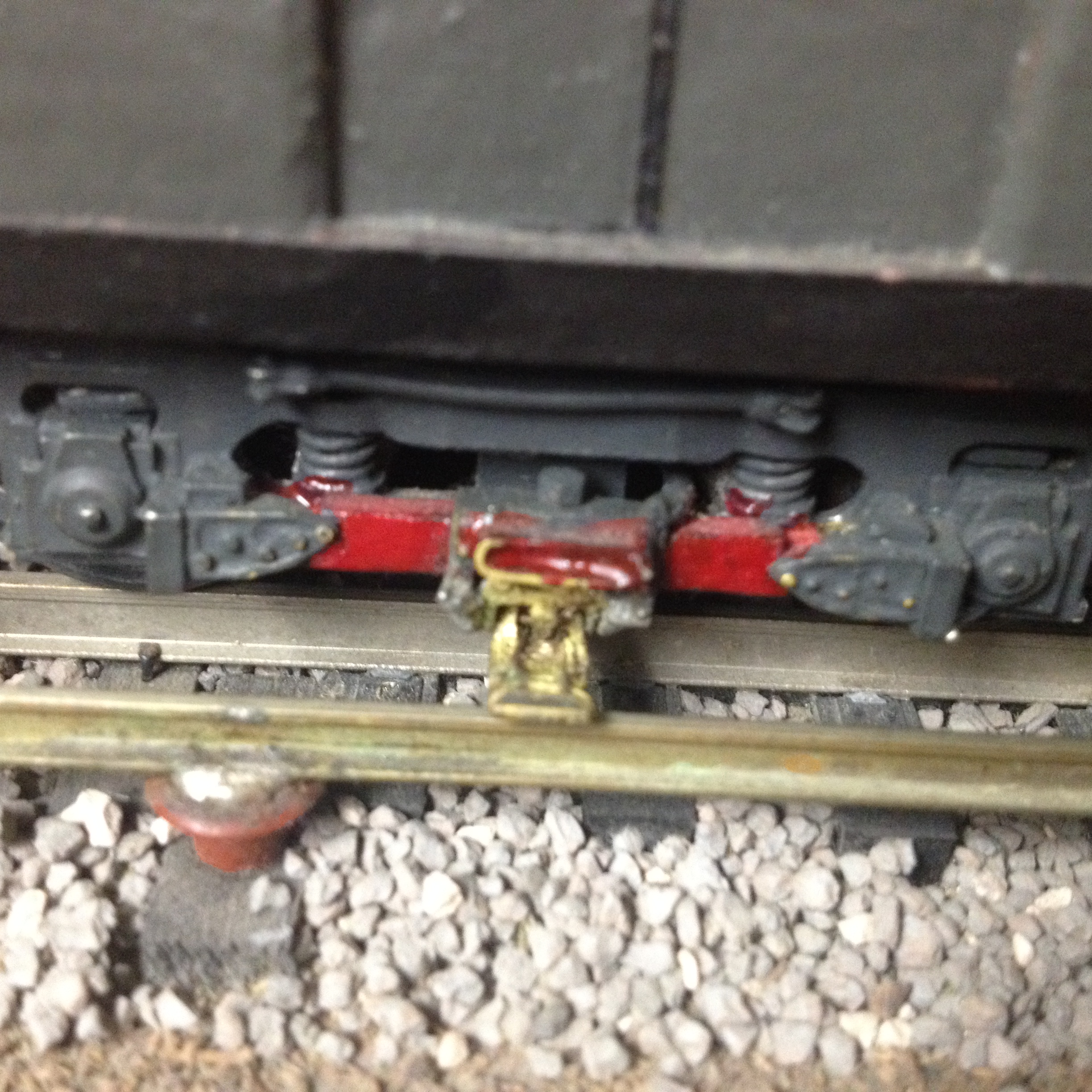
The shoe beam can be made from wood or plastic strip, cut to fit snugly between the brackets and super glued into place. The shoe/hanger assembly can be super glued (as in photo on left) or screwed on from the top (photo on right).
Build NYC Style Elevated Structure - This page describes construction techniques and suggestions for creating scale model El structure.
We hope you found this article to be informative and helpful. If there are any questions or suggestions please email Steven Olsen
![]()
![]()

Created on: 03-06-2017
Updated: 03-08-2017